


When a mold is built, it is essential that it fits and functions according to its design specifications. The mold operates as part of a system that includes the machine and other auxiliary equipment, making it crucial to optimize all points of interface between these components. Neglecting this can lead to delays in launching the part into production, increased product costs or reduced mold lifespan due to premature wear.
Here are some straightforward and practical guidelines to ensure that your newly built mold or existing mold fits properly in the injection molding machine and operates at its maximum capacity. Regardless of how well a mold is constructed, it won’t be effective if the machine cannot meet the necessary molding requirements to produce quality products.


In Part 1 of this two-part series, we will focus on the sizing and specifications of the machine clamp. The clamp is where the mold is mounted and it is also where the forces are applied to the mold via the clamp tonnage. So, it is important that the machine clamp is configured correctly to prevent mold damage, avoid interface mismatches and ensure it operates quickly enough to meet cycle targets.
Following is a list of seven considerations and tips to ensure that the mold will run at its intended speed throughout its lifespan.
1. Tie bar spacing and tie bar size: This assessment is necessary to determine whether the mold will fit into the machine and if the parts can be manually ejected without interfering with the machine's tie bars. Ideally, the mold should fit within the inner diameters of the tie bars; however, at a minimum, the projected areas of the parts should be entirely within the tie bars. This ensures adequate support for the mold, as there can be “pull-in” of the platen near the tie bars, which may lead to premature wear of the mold parting line.
2. Stroke and shut height: The mold needs to be physically compatible with the machine, allowing it to open and close to eject the parts effectively. This means the mold must be thick enough to fit into the machine when it is at its smallest shut height, while also being thin enough to fit when the machine is at its maximum shut height. Figure 1 illustrates the different terminology related to stroke and daylight in a molding machine.


Figure 1 (Top) Toggle machine; (Bottom) Two-platen machine. Source | Milacron
A mold should always be designed to enable parts to drop freely, even if automation will be used to remove the parts during regular production. This is so that the system can be run in semi-automatic before the automation is engaged. As a general guideline, the required mold opening stroke should be at least 2.5 times the height of the part.
There are two main types of molding machine clamp opening mechanisms: those that use toggles (linkages) and those that rely on pistons (hydraulics) (see Figure 1). It's important to note that daylight (the largest opening between platens when the clamp is fully open) is calculated differently for each type of machine.
- Toggle machine daylight calculation: The stroke available is independent of the daylight. Therefore, the maximum stroke is always available at each shut height.
Toggle maximum daylight = Maximum mold shut height + Stroke
- Piston machine daylight calculation: The available stroke decreases as the shut height of the mold increases. The maximum stroke of the machine is achieved at the minimum mold shut height.
Piston maximum daylight = Minimum mold shut height + Maximum stroke
3. Mold and ejector rod mounting locations: The locations of the mounting holes or clamp slots on the mold must align with the patterns and available holes on the machine. Before designing the mold, it is essential to know the machine's mounting pattern, the positions of the ejector holes, and the sizes of the ejector rods. While most machines adhere to industry-standard mounting and ejector patterns such as SPI and EUROMAP, it is crucial to verify this information, as some machines may have modified hole locations or may not follow the full standard patterns.
If the locations of the ejector rod locations on the mold do not match the machine pattern, an ejector box may be necessary to ensure compatibility with the machine's ejector positions. However, adding an ejector box can consume space within the machine and increase weight and costs. So, it's essential to understand this requirement before beginning the mold design process.
4. Locating ring size: The locating ring aligns the mold to the machine and facilitates installation. While there are several industry standards, most molds use either a 4-inch (101.6 mm) or a 120 mm locating ring.
5. Clamp tonnage required: To prevent the mold from flashing or opening during injection, it is essential to determine the clamp tonnage required by the mold and then ensure that the machine has ample tonnage to hold the mold closed. This involves calculating the injection pressures necessary to fill the part and then calculating the projected opening area that these forces will act upon. The required clamp tonnage can be calculated using the formula below:
Equation 1: Tc = Pinj x Ap x number of cavities x SF
Where:
Tc = clamp tonnage (metric tons or imperial tons). Conversion: 1 metric ton = 1.1 imperial tons
Pinj = Peak injection pressure (psi or kPa)
Ap = projected area per part (in2 or cm2) + cold runner (area where pressure acts to open clamp)
SF = safety factor = 1.2 at a minimum
Determining the value of the peak injection pressure (Pinj) can be challenging. In general, the injection pressure at the machine nozzle is adjustable, ranging from low values up to a maximum of about 140 MPa (20,000 psi) in most molding machines. Some high-performance machines can reach pressure levels of 200 MPa (29,000 psi) or even higher. This pressure is typically displayed on the machine's Human-Machine Interface (HMI).
Even though the machine may produce plastic pressures of up to 29.000 psi, by the time the plastic passes through the machine nozzle orifice, runners and gates, the pressure is significantly reduced due to pressure losses from friction and viscosity.
Computer-aided engineering (CAE) simulation software can most accurately estimate injection pressures in the mold when the boundary conditions are well understood and the relationship between plastic viscosity, temperature and shear is correctly modeled.
If the mold designer does not have access to modeling software, there is an effective rule of thumb that can be used. The rule of thumb for calculating clamp size involves using an empirical factor known as RCT, which is applied to the projected area of the mold (see Equation 2).
First, calculate the projected area (Ap) of the mold parts. To do this, calculate the planar area of the part (see Figure 2) to approximate the area or calculate it using CAD software and then multiply that area by the number of cavities.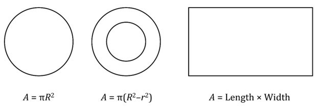
Figure 2: Examples of planar areas for the calculation of clamp tonnage. Source | Oasic Consulting
In two-plate (cold runner) molds, the projected area of the runner system should be included in the total projected area of the cavities. For larger products, the area of the runners is typically small and not a significant factor compared to the cavity areas. However, for smaller products, the area of the runners can be substantial and may be comparable to the projected area of the parts, so it must be taken into serious consideration.
To determine RCT for the part to be molded, refer to Table 1. With this information, you can now calculate the required clamp tonnage.
Equation 2: Tc = Ap x # of cavities x RCT
Where:
Tc = clamp tonnage (metric tons or imperial tons). Conversion: 1 metric ton = 1.1 imperial tons
Ap = projected area per stack (in2 or cm2) (area where pressure acts to open the clamp)
RCT = required clamp tonnage from Table 1 (this number includes a safety factor of 1.2)
If a stack mold is being considered, calculate the tonnage for one face and add 10% for every additional level of the mold.

Table 1. Clamp tonnage requirements by wall thickness or plastic flow characteristics. Source | Oasic Consulting
6. Platen rigidity and parallelism: When the mold is mounted on the platens, it is essential that the platens are thick and rigid enough to support the weight of the mold without deflecting. Check the maximum allowable weights for both the moving and stationary platens, which should be available in the machine manufacturer’s specifications. Over time, wear can cause the platens to sag or deflect. To ensure that the machine remains properly aligned, you should regularly check the level of the machine and the alignment of the platens.
The machine level and parallelism should be as close to zero as possible, but generally, a deviation of 0.001 to 0.002 inches (0.025 to 0.05 mm) is acceptable for machines under 500 tons.
7. Clamp speed (or dry cycle): This is the time for the mold to open to an industry-standard distance, eject the part and then close again. Since the mold must operate within a target cycle time, it is important to ensure that the machine can perform a dry cycle quickly enough to meet the overall cycle requirements.
For thin-wall, fast-cycling applications, the dry cycle time should ideally be between 1 and 2.5 seconds. For most other applications, it can range from 3 to 5 seconds.
Ensuring that the clamp of the injection molding machine is correctly sized is crucial. This guarantees that the mold fits properly in the machine, prevents damage and allows for the production of high-quality parts throughout the mold’s expected lifespan.
Part 2 covers machine injection sizing considerations.


Related Content

How to Implement a Remote Validation Process
A review of the setup and use of a remote mold validation kit.
Read More
What Is Scientific Maintenance? Part 1
How to create a scientific maintenance plan based on a toolroom’s current data collection and usage.
Read More
Considerations for Assessing Robotics Requirements
For this summer school basics series, Pellet to Part explores each stage of the plastic injection molding process. Knowledge of part de-molding, end-of-arm tooling construction, part defects caused by the mold-robot interface and available automation options is key for suppliers looking to add greater value.
Read More
Preparing for Takeover Tooling
For this summer school basics series, Pellet to Part explores each stage of the plastic injection molding process. With the right preparation, moldmakers can insulate themselves from takeover tooling crises and add greater value to the molder.
Read MoreRead Next

MMT Chats: Giving Back by Answering the Moldmaking Education Need
MoldMaking Technology Editorial Director Christina Fuges checks in with Bruce Catoen, an executive advisor at OASIC Consulting. Bruce started out in moldmaking, eventually becoming an industry consultant and taking time to work on his passion project the “Injection Mold Design Handbook” as a way of giving back to the industry that has given him so much. This episode is brought to you by ISCAR with New Ideas for Machining Intelligently.
Read More
It Starts With the Part: A Plastic Part Checklist Ensures Good Mold Design
All successful mold build projects start with examining the part to be molded to ensure it is moldable and will meet the customers' production objectives.
Read More
How to Manage Wall Thickness Changes in Your Mold Design
To ensure even filling and cooling, consider wall section transitions, corners and fillets, ribs and bosses, lip and rim designs and CAE flow simulation software.
Read More